What “industrial endoscope camera” usually means (and who this guide is for)
If you searched “industrial endoscope camera,” you’ve probably seen everything from $30 phone borescopes to specialized inspection systems. In practice, the term usually refers to a camera-on-a-probe (with integrated lighting) used to see inside confined spaces—either as a finishedKey points to align on before you compare anything:
Key points to align on before you compare anything:
- This guide is written for engineering and sourcing teams (US market) who need predictable inspection results and fewer integration surprises.
- There are two common paths: buy a finished borescope/videoscope or build/ship a product that embeds an endoscope camera module.
- “Industrial” is less about the label and more about your environment, workflow, and verification requirements.
Boundary conditions
- Different vendors use “endoscope,” “borescope,” “inspection camera,” and “videoscope” inconsistently—focus on function and system completeness.
- Image quality depends on geometry, surfaces, lighting, and the full signal path (camera + cable + host).
With that scope set, a short definition and a “what to decide first” box will save you a lot of time.
Industrial endoscope camera vs borescope (and what to decide first)
With the scope clarified, here’s the fastest way to interpret what sellers mean. An industrial endoscope camera is typically a borescope/inspection camera: a small camera head on a rigid or flexible probe with illumination, designed to view hard-to-reach cavities.
Common terms you’ll see (practical buying meaning)
| Term you see | Usually means in industrial listings | What to check so you don’t mis-spec |
|---|---|---|
| Endoscope camera | Often used interchangeably with borescope (industrial) | Is it a complete tool or just a camera module? |
| Borescope | Inspection camera on a probe (rigid or flexible) | Probe diameter/length, articulation, durability needs |
| Videoscope | Often implies a more complete “system” (display/recording) | What’s included: screen, recording, software, accessories |
| Inspection camera | Broad category (borescopes plus other inspection devices) | Whether it fits your exact use-case and environment |
| Camera module | OEM component for embedding into your device | Interface, drivers, tuning, sealing, integration responsibility |
What to decide first (before comparing specs):
- Are you buying a finished inspection tool, or embedding a camera module in your product?
- What’s the inspection geometry (working distance, view angle, “how close can you get”)?
- What’s the surface/environment (reflective metal, oily residue, cleaning process, splash/immersion)?
Boundary conditions
- “Endoscope” can be used for industrial inspection without implying medical requirements; don’t infer compliance from the word alone.
- Two items with the same “resolution” can perform very differently depending on optics and lighting.
Once you decide whether you’re buying a tool or building a product, the rest of the choices become much more concrete.
Decide your path: buy a finished borescope vs build with an OEM camera module
Now that the terminology is unambiguous, make the buy vs build decision early. If you need inspection capability quickly with minimal integration work, a finished borescope/videoscope is usually the right choice; if you’re shipping a product that includes inspection imaging, you’ll typically want an OEM endoscope camera module.
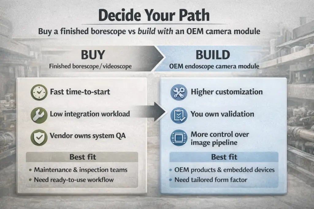
Buy vs build comparison (engineer + sourcing view)
| Decision factor | Buy a finished borescope/videoscope | Build/ship with an OEM camera module |
|---|---|---|
| Time to start using it | Fast (ready-to-use workflow) | Slower (integration + validation required) |
| Custom form factor | Limited to catalog options | Higher (sensor/lens/housing/cable can be tailored) |
| Integration workload | Low (vendor already integrated system) | Higher (host, drivers, power/EMI, mechanics, validation) |
| Control over image pipeline | Limited | Higher (more control, but more responsibility) |
| Environmental hardening | Varies by model; must verify | Can be designed to your exposure scenario (must validate) |
| Best fit | Maintenance/inspection teams | OEM products, embedded devices, specialized probes |
What shifts to your team when you embed a module:
- You own the host-side choices (OS/SoC/ports, driver stack, latency expectations).
- You own the mechanical integration (probe routing, strain relief, sealing interfaces).
- You own acceptance criteria and validation (what “good enough” means, and how you’ll test it).
Boundary conditions
- A module project can be straightforward or complex depending on how tight your mechanical envelope is and how strict your image/ingress requirements are.
- Any schedule, MOQ, or production claims should be confirmed per project and written into your commercial agreement (not assumed from marketing).
A short requirements checklist is the easiest way to reduce back-and-forth—whether you’re buying a tool or requesting an OEM quote.
Quote-ready requirements checklist (so suppliers can answer fast)
After you pick a path, the fastest progress comes from writing the requirements in a way suppliers can quote and engineers can validate. A quote-ready checklist also prevents “sample looks great, integration fails” loops.
Use this as a minimum set of inputs:
- Inspection geometry
– Target working distance range (how close/far the camera must focus)
– View direction needs (front view only vs side/dual view)
– Field of view preference (wide coverage vs reduced distortion) - Mechanical envelope
– Maximum probe/head diameter and length constraints
– Cable routing constraints (bends, movement, strain relief expectations)
– Mounting constraints near the camera head (alignment stability) - Environment & cleaning
– Dust/fluid exposure (splash vs immersion; oil/coolant; cleaning agents)
– Temperature and vibration expectations (operating vs storage) - System constraints (if embedding)
– Host platform (OS/SoC, available ports, CPU budget, power constraints)
– Interface preference or constraints (USB vs MIPI CSI-2; long-cable concerns) - Image acceptance criteria
– What defects must be detectable (scratches, cracks, corrosion, blockage)
– Example reference images (good/bad) and test scenes you’ll use
Boundary conditions
- If any “must-have” constraint is unknown (e.g., working distance or maximum head diameter), feasibility and cost can vary widely.
- For embedded projects, the final image is an end-to-end system outcome, not just a camera-head outcome.
With those inputs in hand, you can evaluate camera specs based on what actually changes inspection results.
Specs that actually change inspection results (optics + lighting + sensor/ISP)
With buy vs build settled, it’s time to prioritize the specs that control what you can really see. In industrial inspection, optics + illumination + sensor/processing usually determine usable detail more than resolution alone.
Spec → what it changes in practice
- Working distance & focus behavior: Determines whether the region you care about is actually sharp at the distance you can physically reach.
- Field of view (FOV): Wider FOV shows more area but can increase distortion and reduce edge clarity if optics aren’t matched to the use-case.
- Depth of field (DOF): Impacts how much of the scene stays acceptably in focus when distances vary in a tight cavity.
- Illumination geometry: Controls glare, hotspots, and shadowing—often the difference between seeing a defect and missing it.
- Sensor sensitivity + noise behavior: Matters in low-light or when exposure must be short (movement); interacts with the lighting design.
- ISP/tuning (image processing): Affects color consistency, noise reduction, sharpening, and exposure behavior—especially on reflective surfaces.
A quick scenario-to-priority map
| Your inspection reality | Specs that rise in priority | Why |
|---|---|---|
| Shiny/reflective metal | Illumination geometry, exposure behavior, tuning | Glare can hide defects even at high resolution |
| Oily/wet surfaces | Lighting + lens coatings/cleaning tolerance, sealing approach | Reflections + contamination are common failure modes |
| Tight spaces with unknown distances | DOF, focus stability, working distance | “Can’t get close enough” is a geometry problem |
| Moving probe / vibration | Exposure behavior, motion artifacts, cable reliability | Stability often beats headline specs |
Boundary conditions
- There is no universal “best” resolution, LED count, or single-number spec that guarantees success—your geometry and surfaces drive the outcome.
- The host pipeline (compression, processing, display) can change perceived detail vs a camera-only demo.
To make these trade-offs easier to apply in a spec sheet and test plan, a compact “spec-to-impact” map helps.
Quick spec-to-impact map (what each spec changes in practice)
If you want a reusable way to translate “what we need to see” into “what we need to specify,” start with these mappings:
- If you’re missing detail on reflective surfaces, adjust lighting geometry and exposure/tuning before assuming you need more pixels.
- If defects appear only near the center of the image, check lens distortion/edge performance and whether your FOV is too wide for the task.
- If images look sharp in the lab but not in the field, validate working distance and contamination/cleaning effects.
Boundary conditions
- Avoid hard thresholds unless you have validated them on your parts; use representative test scenes and acceptance criteria.
Once image requirements are clear, the next biggest decision for embedded designs is whether your host and cable path favor USB or MIPI.
Interface & architecture: USB vs MIPI (and when cable path changes everything)
After you know what image you need, choose an interface your host and mechanical routing can support. In most embedded designs, USB is chosen for integration simplicity while MIPI CSI-2 is chosen for tighter embedded camera integration—but the cable path can change the answer.
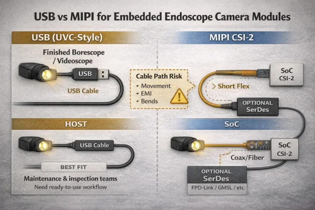
USB vs MIPI vs “consider long-cable architecture”
| Constraint you have | USB (often UVC-style) | MIPI CSI-2 | Consider SerDes (GMSL / FPD-Link context) |
|---|---|---|---|
| Need plug-and-play host integration | Often easier on many platforms | Typically requires CSI-2 support in the host | Often used when cable reach/robustness dominates |
| Tight embedded system design | Possible, but may add overhead | Common choice for embedded camera paths | Used in some long-reach camera architectures |
| Cable path is long / moves / harsh | Can become challenging depending on design | Usually short-reach; routing can be sensitive | Designed for robust video transport over a single cable (system-dependent) |
| You need predictable driver behavior | Often standardized via USB video class approach | Depends heavily on SoC + OS + camera stack | Depends on serializer/deserializer + host integration |
A few practical reminders:
- USB Video Class documentation exists as a USB-IF document set; it’s a helpful reference when you’re aiming for broad host compatibility. (usb.org)
- MIPI CSI-2 is described by the MIPI Alliance as a widely implemented embedded camera interface; your real constraint is whether your chosen SoC/board supports it. (mipi.org)
- For long-cable camera links, SerDes technologies (e.g., FPD-Link, GMSL) are commonly discussed in automotive/embedded contexts and can be relevant when the cable is the dominant risk. (ti.com)
Mini cable-path risk checklist (use before you “pick an interface”)
- Does the cable move (articulation, vibration, frequent handling)?
- Are there tight bends or repeated bend cycles near the probe handle/head?
- Are there strong EMI/noise sources nearby (motors, inverters, welding equipment)?
- Is the connector exposed to fluids/cleaning, creating corrosion or leak risks?
Boundary conditions
- “Long cable” does not have a single universal cutoff—validate with prototypes and your real routing, connectors, and EMI environment.
- Host support matters as much as interface capability; pick the interface that your platform can support reliably.
Once the architecture is plausible, the next step is checking the mechanical reality—because probe failures are often mechanical, not electrical.
Probe-head mechanics: size limits, durability, and common failure modes
With the interface direction set, validate the mechanical constraints that decide whether the design survives real use. Probe head size and reliability are usually limited by optical alignment space, illumination space, sealing interfaces, and cable strain relief.
Common constraints that make “smaller” harder:
- You need physical space for lens alignment and stable mounting.
- You need space for illumination that doesn’t overheat or cause hotspots.
- You need robust sealing and strain relief—often the first real-world failure points.
Failure-mode checklist (what to watch and how to prevent it)
- Cable fatigue near the handle/head: add strain relief, reduce sharp bends, specify bend-cycle expectations.
- Seal failures at joints/connectors: define the exposure scenario and ensure the weakest interface is included in tests.
- Optical contamination (fogging, debris): plan cleaning and handling; consider protective windows and maintenance procedures.
- Alignment drift after shocks: use mechanically stable mounting and verify with drop/vibration-like handling appropriate to your use.
Boundary conditions
- Reliability depends on usage cycles, handling, and environment; a bench demo rarely represents field stress.
- Mechanical constraints often force trade-offs: smaller head can mean tighter tolerances and higher consistency risk.
If the mechanics are feasible, lighting is usually the next reason “high-resolution” devices still underperform in real cavities.
Illumination in dark/reflective/oily spaces: reducing glare and hotspots
With mechanics in place, focus on lighting—because glare can hide defects more effectively than low resolution ever will. The most practical approach is to treat illumination as a geometry problem: angle, diffusion, and exposure behavior determine whether highlights wash out details.
Do / don’t for glare control:
- Do test lighting with the actual surfaces you inspect (polished metal behaves differently than matte plastic).
- Do consider diffusion or light guides when direct LEDs cause hotspots.
- Do validate exposure behavior on both bright highlights and dark regions in the same frame.
- Don’t assume “more LEDs” is the fix; placement and diffusion often matter more than quantity.
- Don’t judge performance from a single still image; probe movement can change reflections drastically.
Boundary conditions
- The best lighting approach depends on working distance and surface reflectivity; prototype with representative parts before you lock the design.
Once lighting is under control, environmental failures (fluids, dust, cleaning) become the next major risk—especially when “waterproof” is treated as a marketing word.
“Waterproof” in real use: how to specify ingress protection and verify tests
After image performance is acceptable, specify environmental protection in a testable way. “Waterproof” is only meaningful when it’s tied to a defined protection scheme and test conditions—IEC describes IP ratings as a way to grade resistance to intrusion of dust and liquids (IEC 60529 context). (iec.ch)

Specify (what to write into your requirement)
- Exposure type: splash, rinse, immersion, pressure spray (if applicable)
- Fluid type: water vs oil/coolant/cleaning chemicals (they behave differently)
- Duration and temperature conditions you expect during use/cleaning
- Which interfaces are exposed: probe head only, cable, connector, handle
- Post-exposure expectations: fogging tolerance, image clarity, connector function
Verify (what to ask for, or what to test)
- Test conditions and pass criteria (not just a claimed IP number)
- Whether the weakest interface (connector/joint) was included in the test setup
- Repeatability: whether performance holds after handling, bending, or reassembly
- If automotive context is relevant, note that ISO 20653 addresses IP code protection for electrical equipment in road vehicles. (iso.org)
- For third-party validation, accredited labs often describe IP testing as enclosure evaluation “per IEC 60529.” (intertek.com)
Boundary conditions
- An IP claim without test conditions is not actionable; treat it as incomplete until you see the scenario and pass criteria.
- Sealing performance can degrade with handling and maintenance; include realistic usage and cleaning in your validation.
With environmental requirements defined, you’re ready to plan an OEM integration workflow that prevents “it works on the bench” surprises.
OEM integration workflow: requirements → prototype → tuning → validation
With requirements in writing, integration becomes an execution problem rather than a guessing game. A reliable OEM endoscope camera module integration typically follows a repeatable workflow from feasibility through validation—especially when you need consistent images in real environments.

A practical 8-step workflow
- Freeze the requirements (geometry, environment, host constraints, acceptance criteria).
- Select architecture (USB vs MIPI; cable path risk; mechanical envelope).
- Prototype samples (camera head + illumination + preliminary housing/cable).
- Bring-up on the host (streaming, drivers, power stability, basic controls).
- Tune for your scenes (exposure behavior, noise/sharpening trade-offs, color consistency) using representative targets.
- Mechanical verification (strain relief, bending/handling, alignment stability).
- Environmental verification (exposure scenario, cleaning, sealing interfaces).
- Pilot and consistency checks (batch-to-batch image consistency under your acceptance criteria).
Where standards help (without overpromising):
- For USB designs, the USB-IF maintains the USB Video Class document set, which is often referenced when aiming for standardized video device behavior on hosts. (usb.org)
- For MIPI, the MIPI Alliance provides an overview of CSI-2 as an embedded camera interface; the practical constraint is platform support and integration stack. (mipi.org)
Integration risk checklist (common “gotchas”)
- Power noise or unstable grounding causes intermittent artifacts or dropouts
- Cable movement + weak strain relief causes intermittent failures over time
- “Great sample image” fails to reproduce without defined acceptance criteria and test scenes
- Environmental exposure was tested on the head but not on the connector/joint
Boundary conditions
- The exact steps differ by platform and interface, but the need for defined acceptance criteria and representative scenes is universal.
- Image results depend on the full pipeline (camera + cable + host processing + display/compression).
Once you understand the workflow, it’s much easier to talk about customization realistically—what can change, and what the constraints actually are.
Customization menu for OEM projects: what you can change, what constrains it
Now that the workflow is clear, treat customization as a controlled set of knobs rather than a wish list. Most OEM projects customize a combination of sensor, lens/FOV, illumination, housing diameter, cable/connector, and sometimes firmware/tuning—but constraints often come from geometry, environment, and platform support.
Common customization menu (with typical constraints)
| Component | Common customization options | Common constraints / trade-offs |
|---|---|---|
| Sensor | Sensitivity, dynamic range targets, size constraints | Availability, power/thermal budget, tuning effort |
| Lens / FOV | Wider vs narrower FOV, focus distance behavior | Distortion vs coverage, DOF limits, mechanical stack-up |
| Illumination | Ring vs directional lighting, diffusion/light guides | Glare control, heat, space in the head |
| Housing / head diameter | Head size, window material, sealing approach | Tolerance sensitivity, sealing interfaces, manufacturability |
| Cable & connector | Length, shielding, connector type, strain relief | Cable movement fatigue, EMI, sealing at connector |
| Firmware / tuning | Exposure behavior, noise reduction, color consistency | Platform dependence, iteration time, validation scenes |
If you’re evaluating a supplier’s customization capability, check whether they explicitly describe customization scope (dimensions, component selection, etc.) and which application domains they support; Supertek’s customization page, for example, describes module dimension customization and application areas such as industrial and embedded vision. (supertekmodule.com)
Boundary conditions
- Smaller heads and harsher environments tend to increase validation effort because tolerances and sealing become more sensitive.
- Some requests are limited by component availability or host platform constraints; a feasibility check is faster than assuming.
Before scaling, the final safeguard is verification and QC planning—so you don’t learn about variability after you’ve shipped.
Verification & QC before scaling: acceptance criteria and practical tests
Before committing to volume, define what “good” means and test it repeatably. The most effective pre-production plan combines image acceptance criteria with mechanical/environmental checks that reflect real use.
Acceptance criteria checklist (make it measurable)
- Focus/clarity at the required working distance range (with your test scene)
- Field-of-view coverage and distortion tolerance (what’s acceptable for your task)
- Illumination uniformity and glare tolerance on representative surfaces
- Noise/low-light behavior under your expected exposure constraints
- Unit-to-unit consistency checks (sample-to-sample variability)
Practical verification checklist (conceptual but actionable)
- Handling/bending checks that match how the probe will be used
- Exposure scenario checks (fluids/cleaning) on the actual weakest interfaces
- Host stability checks (dropouts, power noise sensitivity, thermal stability)
- Pilot run evaluation using your acceptance criteria and documented test scenes
Boundary conditions
- “Pass” depends on your defect-detection needs; align the test scenes and criteria with what your customers/users actually care about.
- Environmental tests that don’t match real cleaning and handling can create false confidence.
With the main decision path covered, the FAQ below answers the most common questions in a snippet-friendly format.
FAQ
- Q: What is an industrial endoscope camera, and how is it different from a borescope/inspection camera?
A: In industrial listings, an “endoscope camera” is usually a borescope/inspection camera: a camera head on a probe with lighting for viewing confined spaces. The practical difference is often not the label but whether you’re looking at a complete inspection tool (screen/recording/accessories) or an OEM camera module meant to be embedded into a device. - Q: When should you buy a finished industrial borescope vs source an OEM endoscope camera module for your product?
A: Buy a finished borescope when you need a ready-to-use inspection workflow quickly with minimal integration work. Source an OEM module when you’re shipping a product that embeds inspection imaging and you need control over form factor, interface, and validation—at the cost of more engineering responsibility. - Q: Which specifications matter most for inspection quality (beyond resolution)?
A: The most important drivers are working distance/focus behavior, field of view, depth of field, illumination geometry, and sensor/processing behavior. Resolution alone can be misleading because glare, distortion, and exposure behavior can hide defects even with high pixel counts. - Q: USB vs MIPI for an embedded endoscope camera—how do you choose (and when does long cable change the answer)?
A: Choose USB when your priority is host integration simplicity and standardized video-device behavior, and choose MIPI CSI-2 when your platform supports it and you want tighter embedded camera integration. If your cable path is long, moving, or harsh, the architecture decision becomes cable-risk-driven and you may need to consider different link approaches and validation rather than assuming any interface will “just work.” (usb.org) - Q: What does “waterproof” mean for an industrial endoscope camera, and what should be verified?
A: “Waterproof” should be tied to defined ingress protection expectations and test conditions, not treated as a vague feature word. Verify the exposure scenario (fluid type, duration, temperature) and whether the weakest interfaces (joints/connectors) were included in the test setup, ideally with conditions aligned to IEC’s IP rating context. (iec.ch) - Q: What are the typical integration steps for an OEM endoscope camera module?
A: A typical workflow is requirements → architecture selection → sample bring-up on the host → tuning on representative scenes → mechanical and environmental verification → pilot consistency checks. The exact steps depend on your host platform and interface, but you should always define acceptance criteria and test scenes early so “working” means the same thing for everyone.
Summary + quote-ready checklist + next steps
Bringing everything together, the most reliable way to choose an industrial endoscope camera is to treat it as a requirements-and-validation problem first. The core decisions are buy vs build, optics/lighting priorities, interface feasibility, and verification discipline.
Key takeaways:
- Start with buy vs build—it determines who owns integration and validation work.
- Prioritize working distance, FOV/DOF, and lighting geometry over headline resolution claims.
- Pick USB vs MIPI based on what your host can support and how risky your cable path is.
- Make “waterproof” actionable by specifying conditions and verifying tests, not marketing wording.
- Define acceptance criteria + test scenes before scaling to avoid batch-to-batch surprises.
Scenario-based next steps (choose the one that matches you):
- If you’re buying a tool: write down your geometry and environment first, then evaluate models against those conditions using a repeatable test scene.
- If you’re embedding a module: prepare the quote-ready checklist (geometry, envelope, host constraints, acceptance criteria) so suppliers can assess feasibility quickly.
- If you’re seeing glare or inconsistent results: iterate on lighting geometry and exposure behavior with representative surfaces before you change sensors.
If you’d like a feasibility discussion for an embedded endoscope camera module, sharing your host platform, mechanical envelope, and acceptance criteria is usually the fastest way to get a meaningful recommendation. (supertekmodule.com)