Choosing a custom autofocus mini USB camera module is not only a product-name search. Two modules can look similar in resolution, board size, or USB interface, but behave differently once they are placed inside a real product.
For OEM buyers, engineers, and procurement teams, the better starting point is the RFQ. A clear RFQ helps the supplier or engineering team understand the application, focus distance, optical needs, mechanical limits, host environment, and validation requirements before recommending a module or sample.
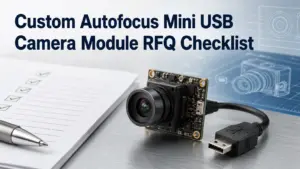
This checklist explains what to prepare before requesting a custom autofocus mini USB camera module, what to compare, and which questions to confirm before sampling.
What to Prepare Before Requesting a Custom Autofocus Mini USB Camera Module
Before requesting a custom autofocus mini USB camera module, prepare your application, working distance, field of view, resolution needs, board-size limit, cable and connector requirements, host OS or software environment, quantity stage, document needs, and validation plan. Autofocus may help when object distance changes, but the final choice still depends on testing in your actual device.
Start With the Application, Not Just Resolution
Resolution is easy to compare, so many buyers start there. But resolution alone does not decide whether a camera module will work in the final product.
A better first question is: what does the camera need to see, from what distance, inside what mechanical space, and under what software environment?
For a custom autofocus mini USB camera module, application details often affect the practical selection more than one isolated specification.
| Selection Factor | Why It Matters | What to Confirm Before RFQ |
|---|---|---|
| Application | Different products need different image behavior, mounting space, and test conditions. | Inspection, kiosk, embedded device, scanner, access control, robotics, documentation-sensitive device, or other use case. |
| Working distance | Focus behavior depends on the distance between the lens and target object. | Minimum, maximum, and typical object distance. |
| Field of view | FOV affects what area the camera can capture at a given distance. | Target scene size, lens direction, and space limits. |
| Resolution | Higher resolution may help detail capture, but can affect bandwidth, processing, and storage. | Required image detail, frame format, and host capability. |
| Board size | Mini modules are often chosen because space is limited. | Maximum PCB size, mounting holes, lens height, and enclosure clearance. |
| Cable and connector | Cable route and connector type can affect assembly and reliability. | Cable length, exit direction, connector type, and assembly constraints. |
| Host system | USB/UVC may simplify driver handling in supported environments, but final behavior still needs testing. | Host OS, software, processor, USB port, and capture application. |
The goal is not to request every possible option. The goal is to give enough application context so the supplier or engineering team can narrow the discussion.
Autofocus vs Fixed Focus: Which One Fits Your Project?
Autofocus is useful in some projects, but it is not automatically better for every mini USB camera module application.
If the object distance changes, autofocus may help the camera adjust to different target positions. If the object distance is stable and controlled, fixed focus may be simpler and more predictable. The right choice depends on the application, expected object distance range, software behavior, and validation results.
| Application Condition | Autofocus May Help When | Fixed Focus May Be Enough When | What to Test |
|---|---|---|---|
| Object distance changes | Targets move closer or farther during use. | Target distance is fixed by the enclosure or fixture. | Focus response at minimum, typical, and maximum distance. |
| User interaction varies | Users hold objects at different positions. | The product guides the object into one fixed position. | Real user handling and repeatability. |
| Space is limited | The module must capture objects at different depths inside a compact design. | The optical path and target distance are stable. | Lens height, focus behavior, and enclosure fit. |
| Software needs control | The application may need focus commands or image tuning. | The application only needs a stable image at one distance. | Whether the selected module and software support required control. |
| Production testing matters | Focus behavior must be checked under real assembly conditions. | A controlled fixture can keep distance consistent. | Sample-to-sample validation under actual lighting and mounting. |

The safest RFQ wording is not “we need autofocus.” A better version is:
We need the camera to focus from [minimum distance] to [maximum distance] while viewing [target size] under [lighting condition]. Please review whether autofocus or fixed focus is more suitable for this application.
RFQ Checklist for Custom Autofocus Mini USB Camera Modules
A complete RFQ does not need to be long, but it should answer the questions that affect technical review.
Use this checklist before asking for a recommendation, sample, or quotation.
| RFQ Item | What to Provide | Why It Helps |
|---|---|---|
| Application | Product type and camera function. | Helps separate general webcam use from embedded/OEM module needs. |
| Target object | What the camera must capture. | Helps review detail, focus, and field-of-view needs. |
| Working distance | Minimum, typical, and maximum distance. | Helps decide autofocus, fixed focus, lens, and validation conditions. |
| Field of view | Target scene width/height at the working distance. | Helps choose lens direction and avoid poor framing. |
| Resolution target | Required image detail or preferred resolution. | Helps balance image detail, bandwidth, and host processing. |
| Board-size limit | Maximum PCB size, mounting holes, lens height, and enclosure space. | Helps avoid samples that cannot fit the product. |
| Cable and connector | Cable length, connector type, exit direction, and assembly path. | Helps check mechanical integration. |
| Host system | OS, software, USB version, processor, and capture application. | Helps identify integration and test requirements. |
| Quantity stage | Prototype, pilot run, or production planning. | Helps frame sample and commercial discussion. |
| Documents needed | Datasheet, drawing, sample images, test report, certificate, or QC document needs. | Helps confirm what is available for the selected module and order context. |

A clear RFQ also reduces back-and-forth. Instead of asking only for a “5MP autofocus USB module,” describe the product environment and the image result you need.
Spec-to-Decision Matrix: What Each Parameter Changes
Camera module specifications are connected. Changing one parameter can affect another. For example, a higher resolution may improve captured detail, but it can also increase data load. A wider FOV may capture more area, but it can reduce detail for a fixed resolution. A smaller board may fit the enclosure, but it can limit connector, cable, or lens options.
Use the matrix below to turn specifications into engineering questions.
| Parameter | What It Affects | Question to Ask | Evidence or Test Needed |
|---|---|---|---|
| Resolution | Detail, bandwidth, processing, storage. | What detail must be recognized or inspected? | Sample images under real distance and lighting. |
| Sensor | Image behavior, format options, low-light behavior, availability. | Is there a preferred sensor, or is performance more important than sensor brand? | Datasheet and sample testing. |
| Lens / FOV | Scene coverage, object size in image, distortion trade-offs. | What area must be captured at the target distance? | FOV calculation and sample image review. |
| Focus type | Ability to handle changing object distance. | Is the object distance fixed or variable? | Focus test across expected distance range. |
| PCB size | Mechanical fit, mounting, thermal and assembly constraints. | What is the maximum board and lens envelope? | Mechanical drawing and enclosure review. |
| Cable | Assembly path, signal reliability, serviceability. | How long is the cable and where should it exit? | Cable routing and host test. |
| Connector | Assembly method and product architecture. | Which connector type fits the main board and assembly process? | Connector drawing and assembly review. |
| USB/UVC behavior | Host integration and software capture. | Which host OS and software will capture video? | Host-side validation with the selected module. |
This matrix is not a substitute for engineering validation. It is a way to make the RFQ more specific before sampling.
USB/UVC Integration: Easier Does Not Mean No Testing
USB camera modules are often attractive because they can simplify integration compared with some other camera interfaces. USB Video Class is a defined USB video-device class, and Microsoft’s UVC documentation describes inbox driver support for UVC-compliant cameras in supported Windows environments.
But USB or UVC wording should not be treated as a guarantee that the module will work in every host device, operating system, cable setup, or software application without testing.
A practical validation path should include:
- Confirm the selected module’s USB and video format behavior.
- Test the module with the actual host device.
- Test the intended cable length and connector arrangement.
- Test the capture software or application.
- Check image behavior under real working distance and lighting.
- Confirm whether focus behavior, exposure, frame format, or other controls meet the application needs.
Please confirm the USB/UVC behavior for the selected module and advise what should be tested with our host OS, software, cable length, and application environment.

Customization Scope to Discuss Before Sampling
A custom autofocus mini USB camera module project may involve more than one customization point. Some changes are optical. Some are mechanical. Some are electrical, firmware-related, documentation-related, or packaging-related.
Do not assume every option is available for every module. Use this section as a discussion map and confirm what applies to your project.
| Customization Area | Possible Discussion Points | RFQ Boundary |
|---|---|---|
| Optical | Lens, FOV, working distance, focus type, image target. | Confirm suitable options for the selected module and application. |
| Mechanical | PCB size, mounting holes, lens height, enclosure clearance. | Provide drawings or space limits where available. |
| Cable and connector | Cable length, connector type, exit direction, assembly path. | Confirm feasibility and testing requirements. |
| USB behavior | USB version, video format, host-side capture conditions. | Validate with the actual host and software. |
| Firmware / settings | Image settings, focus behavior, exposure behavior, control needs. | Ask what can be adjusted for the selected module. |
| Documents | Datasheet, mechanical drawing, test report, certificate, QC document. | Ask what documents are available and applicable. |
| Packaging / order context | Prototype, pilot run, production planning, labeling or packing needs. | Confirm commercial terms during quotation. |

image, test report, certificate, QC document, warranty terms, and commercial terms. Do not assume a document exists until it is confirmed.
Send Application Details for Technical Review
Before requesting a quotation or sample, prepare the details that affect module selection:
- application and target object;
- working distance range;
- field of view target;
- resolution or image-detail requirement;
- board-size and lens-height limit;
- cable length, connector type, and exit direction;
- host OS, hardware, and capture software;
- prototype, pilot, or production quantity stage;
- required documents or review process.
For a custom autofocus mini USB camera module project, the best next step is a technical review based on real application conditions. Confirm available customization options, documents, sample process, MOQ, lead time, and commercial terms before ordering.